General components
The general components of a combined cycle power plant are as follows:
- Gas turbine
- Reheat boiler
- Steam turbine
- Electricity generator
A diagram of a combined cycle power plant, showing a single shaft configuration, is presented in the figure that follows. Each of the components mentioned is described below.
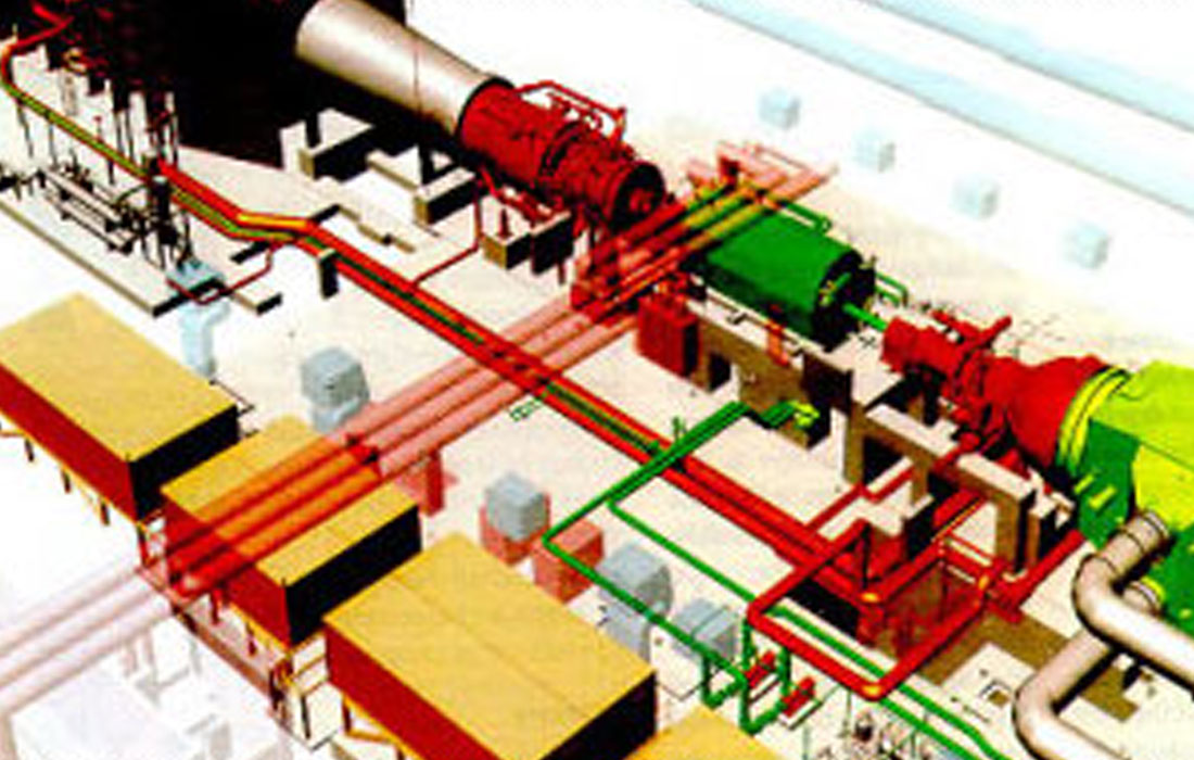
Single Shaft Combined Cycle Power Plant
Gas turbine
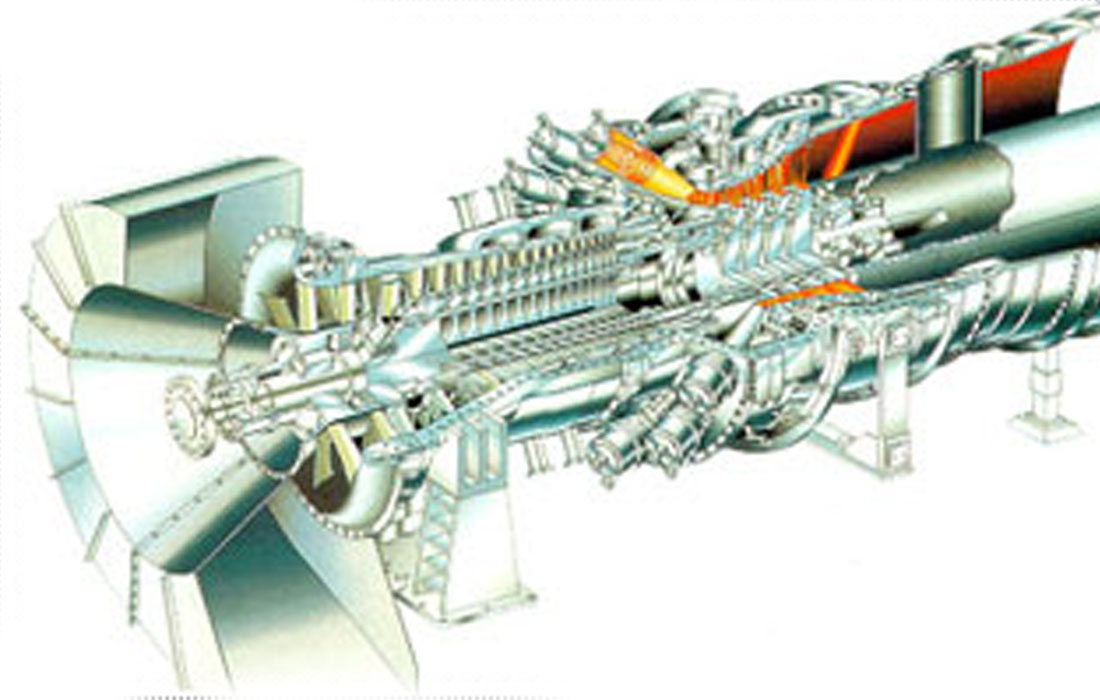
Simplified diagram of a single shaft gas turbine
The gas turbine is the single most important component in a combined cycle power plant. The fact that this type of electric power generation plants has become a competitive thermal process is due essentially to the rapid technological development experienced by gas turbines, especially as regards the improvement in performance of the corresponding thermodynamic cycle.
A gas turbine is a drive turbomachine capable of converting the thermodynamic energy of a gas into a useful pressure on a shaft. In open cycle turbines, the gas is generated in the unit itself and at the time of use. This gas will be the product of the combustion together with compressed air, in a combustion chamber situated before the turbine itself.
The compressed air is obtained from a compressor driven by the turbine itself. The air used as a combustion agent is taken from the atmosphere, with the exhaust gases from the turbine being discharged into the reheat boiler.
The aim, therefore, is to achieve a high pressure and high temperature fluid that can expand in the turbine, releasing its thermodynamic energy, which is converted into the useful pressure on the shaft of the machine.
The figure that follows shows a simplified diagram of a single shaft gas turbine.
The gas turbine is composed essentially of the compressor, the combustor and the turbine itself, forming one solid unit.
The drive element consists of the turbine itself, which, on the one hand, drives the compressor and, on the other, moves the electricity generator (charge). An auxiliary starter motor is required to start up the unit.
Modern gas turbines are usually double shaft type, with one of them being driven by a turbine that in turn moves the air compressor and the second one being driven by a power turbine that moves the corresponding electricity generator, and both shafts can turn at different speeds. Two compressors can also be fitted, one low and one high pressure, driven by one single shaft or by independent shafts.
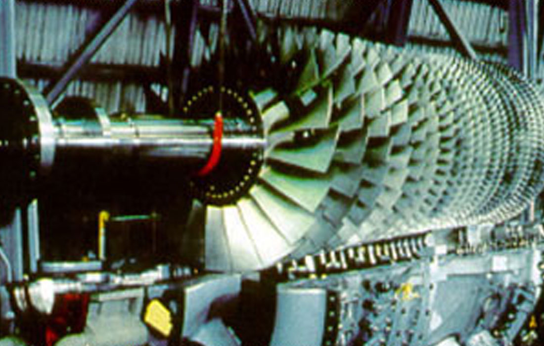
Rotor in a gas turbine
Reheat boiler
The reheat boiler in a combined cycle facility constitute the element of union between the cycle associated to the gas turbine and the cycle associated to the steam turbine.
Its function consists of taking advantage of the heat energy available in the exhaust gases from the gas turbines (energy which is increased in the boilers that have additional combustion available) in order to produce steam, at one or several pressure levels, which in turn is used to drive the steam turbine (combined cycle) or to drive the steam turbine and provide heat energy to the process (combined cycle with cogeneration).
Steam turbine
The steam turbine transforms the thermodynamic energy from the steam generated in the reheat boiler into mechanical energy at the shaft of the machine.
The steam turbines used in combined cycle facilities are of simple design, with relatively low design parameters for fresh steam (corresponding to the level of high pressure in the reheat boiler): temperatures in the 420°C-550°C range and pressures in the 60 bar-130 bar range. In any case, work is taking place in order to increase the pressure, and even supercritical pressures can be reached (higher than 220 bar).
The figure that follows illustrates a simplified diagram of a steam turbine used in advanced combined cycle power plants. It corresponds to a single shaft, double body steam turbine, with intermediate reheating, in the 130 MW-260 MW power output range.
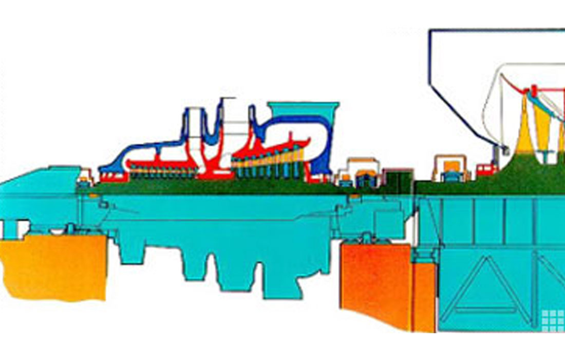
Single shaft steam turbine
In the figure that follows, a simplified diagram of a single shaft, double body steam turbine with intermediate reheating can be seen.
Electricity generator
During the normal operation of the plant, the electrical power generated in the heat cycle will permit the plant’s own consumption to be supplied and the rest of the production to be exported to the grid. In this lies the difference between the gross and the net power output of the plant: the first will be the total power output obtained at the alternator connection terminals, and the second is the result of subtracting the part required for the plant’s own consumption.
The main component in electrical facilities is the alternator that transforms the mechanical energy at the shaft into electrical energy. The configuration used in the majority of combined cycle facilities is that of direct connection to the turbine, using twin pole alternators in these cases. In those systems whose power output is smaller than 50 MW, the habitual use of high speed turbines leads to systems of indirect connection, through a reduction gear device. In these alternatives, four pole alternators are more economical.
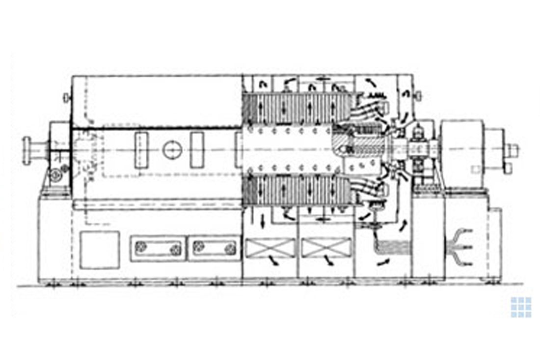
Air cooled electricity generator
Three different types of alternators can be considered, depending on how they are cooled.
- Alternators cooled by air in an open circuit system. These are the best from the point of view of cost and of cooling requirements, but might cause problems with dirt and noise caused.
- Alternators cooled by air in a closed circuit system. Their physical configuration avoids the dirtying and noise problems of the previous ones. The air used for cooling will in turn be cooled in a water operated heat exchanger. This configuration does not give any operating problems. Nowadays, they can be used for power output capacities of around 200MW.
- Alternators cooled by hydrogen. With these systems, greater efficiency levels are achieved than with the previous cases analysed, especially in partial load operation. Against this, the need for special auxiliary equipment, as well as for their own control and monitoring systems, causes considerable design complications in this configuration, as well as an increase in price.
Auxiliary systems
For the correct operation of a combined cycle facility, the main equipment items must be integrated with a series of auxiliary systems:
- Fuel system.
- Air intake system.
- Water supply system.
- Condenser system.
- Cooling system.
- Electrical systems.
- Control and safety systems.
- By-pass and exhaust gases system.