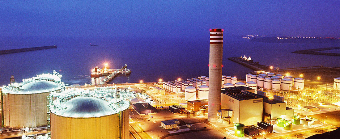
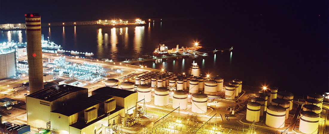
General configuration

The plant has two turbo-alternator units with a gas turbine to produce electricity for the grid through the main transformers. They also supply the auxiliary transformers and a turbo-alternator unit with a steam turbine that directly produces power for the grid through a transformer.
The plant uses three turbo-alternators to produce power, each of them connected to a different turbine – two of them gas turbines and the other a steam turbine – generating 15.75 kV respectively. The gas turbines are 254-MW models and the steam turbine 284 MW.
The steam-turbine alternator uses a main transformer to supply the grid. The transformer is connected by phase-insulated busbars with no bridging connections or switches used.
The energy produced by the gas-turbine alternators is conducted to the main transformers by insulated busbars. The connections to the auxiliary transformers run from these bars.
A switch is fitted between the bridging connecting the auxiliary transformer and the alternator. The switch has a cutoff capacity for the planned ground fault current, which means the auxiliary transformer can be used as a start-up transformer.
The auxiliary transformers have two secondary windings one of which powers the BBG regasification terminal.
The intermediate-voltage busbar (6kV) consists of three sets of bars supplied by the auxiliary transformers and connected to each other by a switch.
The intermediate-voltage bars are made up by a series of metal cabins fitted with internal, three-phase, unpluggable switches with hexafluoride or vacuum circuit breakers. The current and protective devices are adapted to the equipment they supply.
The intermediate-voltage bars connect all the motors with a power rating equal to or in excess of 200 kW as well as the HV/LV transformers, which are used to power low-voltage services.

The low-voltage bars are made up of reinforced metal cabins with front compartments where the switches, meters, and control and protective mechanisms are located. The bars are positioned in the rear section along with the voltage and current transformers, the power bars and the connections for the cables running to the exterior. The switches can be removed and the current is adapted to the equipment they supply.
The low-voltage bars supply the Motor Control Centres (MMC), the battery-charging equipment, and the motors with power ratings between 75 kW and 199 kW.
The motor monitoring centres consist of separate cubicles. These can be removed and are grouped together in accordance with the status of the various motors. They are used to power motors and services with a power rating below 75 kW and a power supply below 150 A.
Two power and lighting units have been fitted to supply power for general services such as lighting, sockets, cabin heating resistors and other services. These are supplied by three transformers of 500, 500 and 120 kVA with a transformer ratio of 400/400-230 V.
Two sets of 110 V batteries complete with chargers and a current distribution panel have been fitted to power the switch control unit, signals, protective devices, the emergency equipment motors, etc. One of the 24 V batteries supplies a direct current.
For services requiring an uninterrupted AC power supply, two 25 kVA (approximately) battery-powered inverters have been fitted. These guarantee AC power supply in the event of a power failure.
The plant also has two 800-kW diesel-powered backup generators. In the event of a general power failure lasting over an hour, the generators can be used to power essential equipment at the plant.

