The plant also comprises the following main auxiliary systems:
Main cooling system
The main cooling system supplies seawater to cool the condenser and the closed cooling water circuit.
It comprises a filter system consisting of fixed and moving grilles (2×50%) and two water circulation pumps (2×50%). It also has a smaller auxiliary pump used for cooling during plant shutdowns.
If one of the filter systems breaks down or needs to be serviced, the plant can continue to function at full capacity with only one filter unit operating.
If one of the water circulation pumps breaks down, the plant can continue at full capacity with a reduction in the power of the steam turbine through loss of vacuum in the condenser.
The system also comprises a pump located in the seawater tank which provides minimum cooling services when the plant is not operating.
The cooling water system also includes a “Tapproge” condenser cleaning system.
Auxiliary cooling circuit
The closed auxiliary cooling circuit serves equipment in the plant that requires a cooling source.
It essentially consists of a raised tank, circulation pumps (3 x 50%), plate-type heat exchangers (2×100%) , pipes, valves, etc.
The system uses demineralised water which has a corrosion inhibitor added to it.
The raised tank is used as an expansion tank and to keep the circuit in overpressure.
Natural gas system
Natural gas is supplied from the regasification terminal (BBG). The gas enters the BBE plant at a single point on the perimeter after passing through the regulating and metering station on the BBG site (2 x 100% lines).
Two fine-mesh filters (2×100%) are installed upstream from the gas turbine.
Two gas heaters (one for each turbine) are programmed to operate before the gas is injected in the turbine for the purposes of improving plant efficiency.
Compressed air system
The compressed air system comprises oil-free centrifugal compressors (2×100%) and two air circuits, one for the instruments and the other for the service system. A storage unit is installed in each of the circuits.
The instrument air circuit comprises a drying unit (2×100%).
Although the two circuits are connected to each other, if the pressure in the services air circuit drops it is cut off and priority is given to the instrument air circuit.
Demineralisation plant
The demineralisation plant, which consists of two demineralisation lines (2×100%), produces high-purity demineralised water.
The plant treats drinking water from the Consorcio de Aguas del Gran Bilbao network. The demineralised water is stored in two 500 m3 tanks.
Waste treatment plant
The various types of water produced at the plant are separated into four categories for treatment prior to its disposal: oily water, process water, rain water and waste water.
Chemical dosing unit
Phosphates are added in the boiler drums. The system comprises six piston dosing pumps, one for each boiler drum, in addition to a reserve pump.
Proportioning of hydrazine and ammonia is carried out the degasifier and is driven by condenser pumps. Each system features two double diaphragm pumps (2×100%).
The chemical dosing units are mounted on a bed and consist of a diluting tank, pumps to fill the tank, a stirring paddle, dosing pumps, etc.
Chlorine and bromide is dispensed in the water circuit by five pumps located in the pump house.
Sampling system
The water and steam samples are taken from the water/steam cycle. The samples are conditioned, analysed and monitored to ensure the plant operates reliably and safely. The analyser is fitted on a sample rack in a room adjacent to the chemical laboratory.
Monitoring of emissions
The plant is equipped with a complete gas emission monitoring system for measuring SO2, CO, CO2, NOx in line with the standards and regulations currently in force.
Fire prevention system
The plant is equipped with a fire prevention system that protects the plant equipment and systems and comprises hydrants, BIEs and fixed extinguisher points (water and foam).
The tank supplying the system is filled with drinking water from the network and can supply the pumps for two hours at maximum flow.
An electric and a diesel pump, both capable of operating at 100% capacity have been installed along with a jockey pump to maintain pressure levels in the network.
In addition to the water-based systems, gas systems have also been installed in the requisite areas as well as portable extinguishers.
The fire-prevention system also features a detection and alarm network controlled by a panel located in the control room.
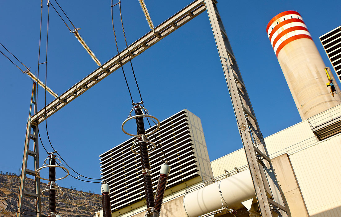
Chimney
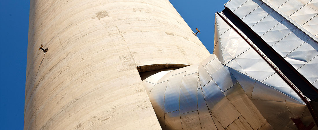
- Height: 125 m.
- Outer diameter of the shaft: 16,9 m.
- Temperature of entry gases: 90°C.
- Diameter of internal pipes: 7,05 m.
- Concrete: 2.832 m3.
- Reinforced steel: 227 t.
- Fire brick: 1.054 t.
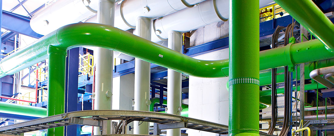
Mechanical systems and pipes
- High Vapour: 127 barg (*), 567°C, 270 t/h per boiler.
- Medium vapour (hot reheating): 26 barg (*), 568°C, 320 t/h per boiler.
- Low vapour: 4 barg (*), 274 °C, 32 t/h per boiler.
- 100% By-passes: 2 of AP, 2 of MP and 1 of BP.
- Condensed Water Supply System:
- Three condensed pumps (3×50%) each of 400 m3/h
- Three high pressure boiler feed pumps (3×50%) of 350 m3/h and 1,770 wcm.
- Three medium and low pressure boiler feed pumps (3×50%) of 145 m3/h and 470 wcm.
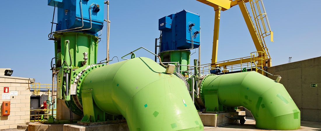
- Main cooling circuit:
- Rated for a heat jump of 8°C.
- Two main pumps of 26,000 m3/h
- One auxiliary pump of 1,000 m3/h
- Two booster pumps of 2,025 m3/h to cool the closed cooling circuit.
- Auxiliary closed cooling circuit:
- Two titanium plate exchangers of 18.4 MW, cooled by means of sea water.
- Three pumps of 1,340 m3/h.
- Other systems:
- Auxiliary vapour system, with a boiler and a flow of 10 t/h., 8.5 bar (*) and 200°C.
- Natural gas systems for a flow of 13.5 kg/s per turbine, 36 bar (*) and 185 °C.
- Water treatment plant with two demineralised water lines of 20 m3/h.
- Treated fireproof water tank of 1,000 m3 and two for demineralised water and one for condensed, each of 500 m3.
- Effluent treatment plant for process, oily, pluvial and untreated waters.
- Water and vapour sampling system.
- Chemical dosing system, adding trisodium phosphate, hydrazine, ammonia, sodium hypochlorite and sodium bromide.
Electrical systems
- Two main transformers for gas turbines: 405/15,75 kV, 315 MVA, ONAN / ONAF1 / ONAF2, tap changers without voltage.
- One main transformer for the steam turbine: 405/15,75 kV, 400 MVA, ONAN / ONAF1 / ONAF2, tap changers without voltage.
- Two auxiliary transformers: 15,75 / 6,3-6,3 kV, 36 / 26-10 MVA, ONAN, tap changer while charged.
- Eight service transformers: 6/0,42 kV, 2 MVA, AN and two isolating generators.
TRANSFORMERS:
- Two main cooling pumps: 1,6 MW, 6 kV.
- Three HP boiler supply pumps: 2,1 MW, 6 kV.
- Three MP/LP boiler supply pumps: 275 MW, 6 kV.
- Two booster pumps: 200 kW, O,4 kV.
- Two pumps in closed cooling circuit: 132 kW, O,4 kV.
- Three condensed pumps: 160 kW, O,4 kV.
- Two generator switches: 15,75 kV, 12.000 A, 100 kA
- Isolated phase bus bars for gas turbines: 12.000 A.
- Isolated phase bus bars for steam turbines: 13.000 A.
MOTORS:
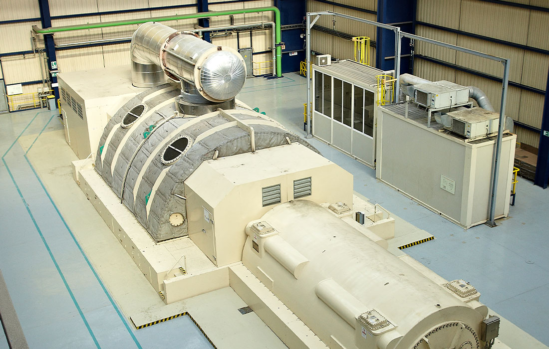
POWER TRAIN:
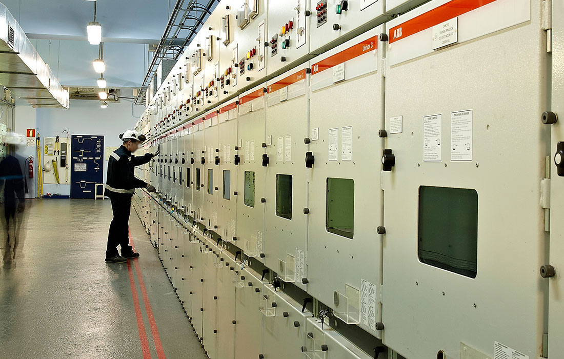
- Forty cabins of 6 kV: 3.150 A, 40kV.
- Five boards of 400V: 3.150 A, 50kV.
- Six MCCs: 800 A, 50kV.
- Two rectifier systems at 125 V DC, 1,850 A
- Two sets of batteries with 58 boxes and 5,940 Ah.
- Two undulators of 50 kVA in 230 V.
- Two diesel generators of 875 kVA.
- Electrical Control System.
- Low voltage distribution.
SWITCHBOARDS:
EMERGENCY SUPPLY SYSTEM:
OTHERS:
Instrumentation and control
- More than 6,000 control signals.
- 200 valves.
- 300 control links.
- 4.000 inputs/outputs.
- Four redundant controllers.
- Ten input/output cupboards distributed per field.
- Control and supervision of “package equipment”.
- 1,500 instruments in total.
- Pressure, temperature, flow and level transmitters.
- Control valves.
- Local indicators.
- Analysis of:
- Cycle: conductivity, pH, silica, dissolved oxygen, sodium, ammonia.
- Exit gases in the chimney: pressure, temperature, flow, CO, CO2, NOX, SO2, O2.
- Cooling water in the discharge: temperature, residual chlorine.
- Effluents in the elimination point: pH.
DISTRIBUTED CONTROL SYSTEM:
FIELD INSTRUMENTATION:
- 100 inputs/outputs.
- “Triple redundant” System.
- 1,800 inputs/outputs.
- One redundant PLC.
- Supervision and remote control from the DSC.
- Independent control from the PLC of:
- Auxiliary boiler.
- Water and effluent treatment plants.
- Seawater filtering system.
- Condenser cleaning system.
- Cycle analysis.
- Chemical dosing.
- Seawater chlorination system.