Gas Turbines
Key Characteristics:
- Unitary power: 254 MW.
- Speed: 3.000 r.p.m.
- Compression ratio: 15,4:1
- Output gas flow: 640 kg/s.
- Combustion temperature: 1.300 °C.
- Temperature of gases: 609 °C.
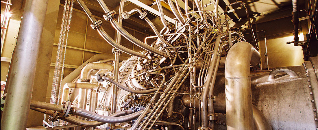
MS 9001 FA gas turbines, designed and built by General Electric, are installed. The electrical generator is connected to the gas turbine by a rigid coupling and is located at the end of the turbine compressor. The gas turbine compressor comprises 18 stages fitted with variable geometry stator vanes for optimal performance at partial loads. Low NOx turbine burners have been installed. The gas turbine is a three-stage model. The turbine-compressor is housed in a horizontally sectioned type casing in order to make inspections and maintenance quicker and easier. The turbine-generator set is started up by the generator acting as a motor (LCI). The gas turbine runs on natural gas only (although it is equipped to burn diesel oil as well) and the exhaust gases pass through the heat recovery steam generators which convert them into energy.
Heat recovery steam generator
Key Characteristics:
- HP vapour pressure: 127 barg.(*)
- HP vapour temperature: 567 °C.
- Hot reheating pressure: 26 barg.(*)
- Hot reheating temperature: 568 °C
- LP vapour pressure: 4 barg.(*)
- LP vapour temperature: 274 °C.
(*) Relative pressure.
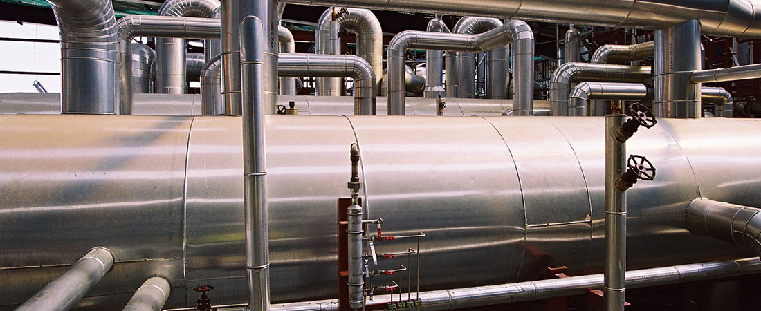
The plant boasts two natural-circulation heat recovery steam generators, designed and manufactured by BWE. The boilers are housed in the same building and feature three pressure levels and a heater chamber.
The boilers follow ASME design criteria and meet the start-up, shutdown and load-change requirements for gas turbines.
The boiler unit comprises the following sections:
- A high-pressure secondary superheater.
- Secondary and primary heater chamber.
- Steam turbine: 281.823 kW.
- High-pressure evaporator unit.
- High-pressure, high-temperature economizer.
- Intermediate-pressure superheater.
- Intermediate-pressure evaporator unit.
- High-pressure, low-temperature economizer.
- Intermediate-pressure economizer.
- Low-pressure superheater.
- Low-pressure evaporator unit.
- Water supply economizer.
The boiler drums and level-monitoring system have been designed to ensure a suitable operating level without excessive venting flows.
Steam turbine
Key Characteristics:
- Unitary power: 281 MW
- Speed: 3.000 r.p.m.
- HP vapour flow: 540 t/h.
- Hot reheating flow: 640 t.
- LP vapour flow (total): 670 t/h.
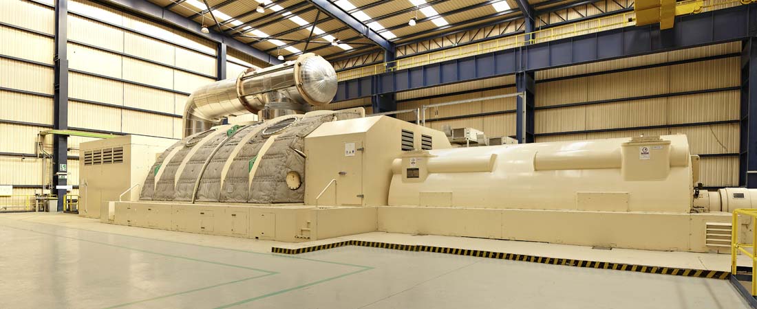
The condensing steam turbine enables reheating and comprises three stages: high, intermediate and low pressure. All the turbine models have been selected for their specific steam conditions and volumetric flow rates and are fitted with the necessary shutdown and control valves for the high, intermediate and low phases.
The steam originating from the two boilers feeds into a single pipe and is led to the corresponding turbine stage (HP, IP, LP).
The low-pressure stage exhaust is positioned lower down and the steam produced is routed to a condenser located underneath the turbine.
In order to assist start-up and shutdown procedures and to enable the gas turbines to operate should the steam turbine trip, it is equipped with HP, IP an LP bypass systems to discharge 100% of the production capacity of the heat recovery steam generator.
Condenser
Key Characteristics:
- Condensed flow: 200 l/s.
- Exchanged heat: 471.000 kJ/s.
- Design pressure: 44,5 mbar.
- Cooling water temperature: 19 °C.
- Heat jump in cooling water: 8 °C.
- Dimensions: 19X8,6X8,4(h)m.
- Absolute weight: 260 t.
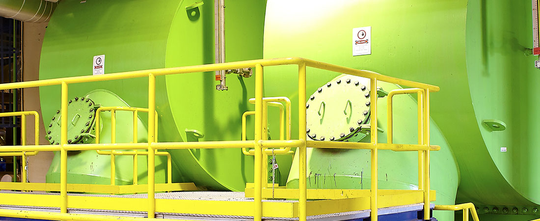
The single-pass steam surface condenser is fitted with titanium pipes and a seawater cooling circuit. It has been designed, manufactured and tested in accordance with the Heat Exchange Institute (HEI) Standard. The plant has been designed to condense the maximum exhaust steam flow from the steam turbine, receive the drain-off from the steam system and to condense the steam flows from the HP, IP and LP bypass systems during the start-up of the heat recovery steam generator, the start-up of the turbine and the tripping of the steam turbine.
The water boxes and the condenser pipes have been designed and hydraulically tested to withstand the pressures exerted as a result of a possible surge in the water circuit.
Steam/water cycle
The high-pressure steam produced in the boilers is carried through a single pipe to the steam turbine's high-pressure stage. There it is expanded and the cold reheat steam is returned through a single pipe to the boilers where it is distributed between them. The cold reheat steam is mixed with the intermediate-pressure superheated steam and reheated in the heater chambers of the boilers.
The hot reheat steam is directed towards the steam turbine's intermediate-pressure stage.
Part of the low-pressure steam produced in the boiler is used in the degasification process. The excess steam is superheated and directed towards the turbine's low-pressure stage through a single pipe.
The steam expanded in the turbine is condensed in a single-pass surface condenser with a seawater cooling circuit. The pressure in the condenser has been optimised in order to ensure high power efficiency.
The non-condensable air and gas that enter or are produced in the water/steam circuit are extracted from the condenser by water ring vacuum pumps.
The level of the hotwell in the condenser is maintained within the preset limits either by allowing water in or by draining off the condensate to the condensate holding tank .
The degasifier has been designed to operate in idle turning mode (approx. 60°C) so that the minimum recommended temperature can be maintained in order to power the boiler economizers and thus make full use of the gas-turbine exhaust gases.
The storage tank in the degasifier is used as a holding tank to compensate for the variations in volume in the water/steam circuit during start-up, shutdown, continuous operating and rapid load changes.
The gases extracted from the degasifier are conducted towards the condenser through the connection between the head of the degasifier and the neck of the condenser.
The supply water is transferred to the boiler by two sets of high-pressure and intermediate/low-pressure pumps.
The high-pressure unit comprises three 50%-capacity pumps supplying the two boilers. The pressure/low-pressure unit comprises three 50%-capacity pumps.
If any of the pumps in a feeder unit break down, the third pump automatically starts operating.
The system features two high-pressure bypasses (one for each generator), two intermediate-pressure bypasses (one for each boiler) and one standard low-pressure bypass. This bypass system is used in the following processes:
- Controlled start-up process
- Controlled shutdown process
- Rapid load changes
- Transitory in case of steam turbine tripping
- Transitory in case of load rejection
- The bypass system is designed to operate with 100% of the heat recovery steam generators' production.